
Allowing sailors to track nearby shipping traffic and to continuously broadcast their own boats position, the automatic identification system (AIS) transceivers available today have been a breakthrough for collision avoidance, communication and distress signaling. PS tester Joe Minick’s field trials carried out in the Dardanelles Strait provides a useful overview of the pros and cons of AIS (see Marine Electronics: AIS Gets Ocean Tested Near Dardanelles Straits). Ralph Naranjo examined how AIS fit into the safety-at-sea picture in his special report, Trends in Safety Gear).
Its important to keep in mind that an overwhelming number of small boats and many ships are still not equipped with AIS, so maintaining a vigilant watch with all available means remains an important aspect of seamanship, especially in coastal waters.
Its also important to be aware of some common technical problems that can interfere with AIS performance. During an offshore race in 2018, some boats reported that the AIS signals of other competitors reportedly disappeared at night. These and other similar incidents prompted the U.S. Coast Guard to publish a safety alert after it identified that some (usually older, non-standard) LED navigation lights can interfere with AIS and VHF (see Coast Guard Seeks LED Input).
A 2018 review of AIS systems aboard Volvo Ocean racing boats turned up a different problem. Even at this high level of racing, AIS equipment on many boats had less than optimal performance, primarily due to installation issues.
Fortunately, both of the above problems can be resolved with proper attention to detail when installing and checking equipment. In this special report, written by renowned offshore navigators Stan Honey and Dan Jowett and supplemented by articles from our PS testers, we take a closer look at ways to ensure your boats AIS/VHF transceiver installation is functioning as it should.
CHOOSING AN ANTENNA
Most marine VHF masthead antennas are mechanically mounted using the coaxial connector. Common VHF whips use a female SO239 socket that mates with a PL259 plug on the coax cable. PL259/SO239 coax connectors (aka UHF) are common, mechanically rugged, and installable without tools, but they are not weather resistant. If you use an antenna with a SO239 mount and so use a PL259 connector on the coax, be sure to follow the notes below in this article to add water resistance.
Half-wave, end-fed antennas are about 36 inches (1 meter) long with a matching transformer at the base. These are the best choice overall for use on sailboats. These antennas provide reasonable gain but are not so directional as to be ineffective when heeled (see “Antenna Gain and VHF Transmission Range“). They do not require a ground at their base.
Half-wave antennas that mount with a PL259/SO239 include the common Shakespeare 5215, and the GAM SS-2 among many other options. Again, if you use an antenna such as these with a PL259/SO239 connection used as a mount, waterproof the connection carefully as described below because the PL259 is not weatherproof.
The V-Tronix MD20N is a half wave antenna made by Shakespeare which uses an N-type connector at its base. This antenna is the best choice for a half-wave antenna because the N-type connector is both mechanically rugged and inherently weatherproof, and so is ideally suited to the challenging environment at the masthead of a sailboat.
Crimping N-type connectors should be done with a special crimper, widely available from radio and telecom supply houses for about $30. Any electronics technician will have the proper tool but it is a tool worth owning.
Quarter wave whip antennas of 15 to 18 inches in length are widely used on racing boats and meet the OSR requirements. Farallon makes an Ultrawhip which mounts using a weatherproof TC connector as its base. The widely used Shakespeare model #5216 uses a PL259/SO239 at its base that needs to be carefully weatherproofed.
All quarter-wave antennas require that the base of the antenna, specifically the shield of the coax, be grounded to the mast at the base of the antenna. Aluminum or carbon masts work fine as a ground/counterpoise.
DC ground warning: You should have only one DC connection between the DC electrical system ground and the hull/keel and the ocean. Generally this connection is at the engine negative terminal or its bus. If the shield of the VHF coax is connected to the aluminum or carbon mast at the masthead (which is essential for a quarter-wave antenna) you will create a second and undesirable DC connection between the electrical system and the ocean via the keel. This is because the mast is usually connected to the keel for a lightning ground.
To avoid the undesirable additional DC ground connection put an inner-outer DC block in the antenna coax. Proper grounding and related topics are also addressed in “Systems Installation,” the first volume in our five-volume ebook “Marine Electrical Systems.”
VHF AIS ANTENNA LOCATION
The Offshore Safety Regulations (OSR) for the offshore racing require that the VHF whip be mounted at the masthead. This makes sense because daytime VHF range, when there is unlikely to be ducting, is limited to line of sight. For you to have a reasonable range (e.g. 7 to 8 miles) to receive a call for help from somebody using a handheld VHF at deck level, sailboats should take advantage of the height of their mast.
The OSRs permit the AIS to either share the primary antenna via an AIS antenna splitter, or to use a dedicated antenna that is mounted at least 3 meters above the waterline. Given that one of the most important uses of AIS is to locate a person in the water wearing an AIS MOB beacon, the masthead location is important if you want to receive AIS MOB beacon signal from the maximum possible range (about 1-3 miles depending on mast height).
Thus, it makes sense to use an AIS antenna splitter and share the masthead VHF antenna for both VHF and AIS. The AIS will not receive while the VHF is transmitting on voice, but AIS MOB beacons repeat their transmissions frequently, and MOBs don’t move very fast, so the shared antenna at the masthead makes the most sense.
VHF antennas should never be mounted closer to one-another than one wavelength, which in the case of marine VHF is nearly 2 meters. Thus it isn’t possible to mount two VHF antennas on the same masthead.

RF CABLE SELECTION
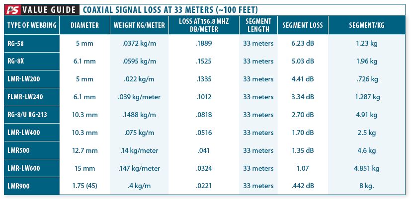
The OSRs require that the coax from the VHF radio and AIS have a maximum loss of 2.2 dB. Add up the loss per meter of the coax and make sure that the total loss of your coax is less than 2.2 dB. Include all segments of coax from the VHF to the AIS antenna splitter, and then to the masthead antenna. Stan Honey has created a handy calculator here.
Losses for some common types of coax (at 156.8 MHz), in dB per meter, are between 0.0324 dB/m for LMR600 and 0.1889 dB/m for RG58.
Coax connectors have essentially zero loss at marine VHF frequencies, and modern AIS antenna splitters have essentially zero loss on receive. If your coax has less than 2.2 dB loss and your VHF whip is at least 15 inches long, your installation will meet the OSRs and will work well. The most common performance problem is water intrusion into the coax at the masthead or at the base of the mast which can also be a wet environment.

RF CABLE INSTALLATION
If possible use water-resistant coax connectors such as Type N or TNC. PL259-SO239 and BNC connectors are not weatherproof and so are less dependable in a marine environment, particularly at the masthead.
Be cautious of quick-connect connectors such as BNC where the bayonet shell is held by springs. These connectors are made for rapid connection and disconnection. They do not provide strong and vibration-resistant mechanical support for the contacts.
If you do use a PL259 connector, unless you are an experienced professional, it is preferred to use a connector with a crimp for the shield rather than the kind that requires that the shield be soldered. A crimp tool only costs about $30, and can also be used on N-Type connectors as well. The PL259 connectors that require that the shield be soldered require significant skill and practice to attach properly, and are nearly impossible to install correctly when sitting in a bosuns chair at the masthead on a windy day. There is a how-to reference at the end of this article.
Don’t skimp on the connectors themselves. Amphenol is a good source of quality connectors. Avoid quick-connect piercing or screw-on connectors for permanent installations.
If you use LMR-LW coax (e.g. lightweight) you must use a connector with a crimp for the shield because the shield braid is aluminum and cannot be soldered with conventional flux and solders.
All coax connectors (including weather resistant ones such as N-type or TNC) should be carefully sealed as described below, but careful sealing is particularly important for PL259 connectors which have no water resistance by themselves.
If a coax connector is used in a wet environment (e.g. the masthead or mast base), fill the interior of the coax connector with silicone dielectric grease (e.g. Dow Corning 4, but there are many equivalents). With no air cavities in the coax connector, there is no place for water to go. The silicone grease adds zero RF loss at any frequency below 1 GHz but adds enormous immunity to water intrusion and corrosion.
Wrap the connector tightly with self-amalgamating tape (e.g. Scotch 2228) for water protection, and then wrap again with vinyl electrical tape (e.g. Scotch 33+) for mechanical protection.
Test the coax loss periodically to detect water intrusion.
LED LIGHT INTERFERENCE
A few older design masthead LED lights (e.g. running or anchor lights) emit noise in the marine VHF band from their switching circuitry. A quick way to test for this is to tune your VHF radio to an unused channel, turn the squelch all the way down so that you can hear the receiver noise, and then turn the masthead lights on and off to see if you can hear them.
Another test that works in a coastal area with lots of AIS contacts is to run your AIS transponder for 10 minutes, and develop an impression of how many AIS contacts there are, and how far the most distant ones are. Then turn on the masthead LED lights, restart the AIS transponder, run it for the same period of time, and compare the results.
Most currently available masthead LED lights are sufficiently well-designed to emit no interference, or just barely noticeable interference, in the marine VHF band. It is worth testing however. Some early and poorly designed masthead LED lights, or LED bulbs used to replace the original halogen bulbs, would nearly deafen a VHF or AIS due to emitting strong RF interference.
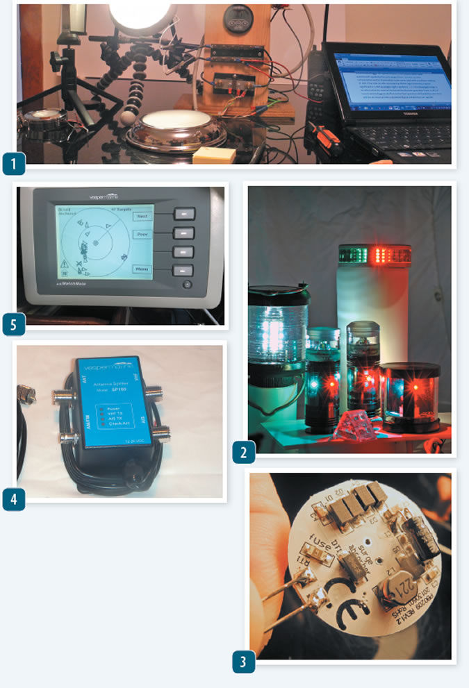
Like most marine electronics, AIS equipment is vulnerable to environmental conditionswater, salt-spray, heat, humidity. Investigate any signs of corrosion or moisture intrusion that can reduce power. Radio frequency interference (RFI) can harm reception. LED nav light should meet US (FCC) and international (CE) standards for suppressing RFI.
- Interior lighting, especially older fluorescent bulbs, and non-compliant LED can interfere with shipboard radios (see “LED Interior Lights“).
- Our navigation light test discovered some lights had higher RFI than others (see ”Practical Sailor Tracks Down the Best LED Tri-color Light“). Look for U.S. Coast Guard certified nav lights.
- The backside of a G4 (12 LED) light disk contains voltage regulator components and a fuse.
- An antenna splitter allows the AIS to share a mast-mounted VHF antenna. This approach ensures maximum reception range, an important feature when trying to locate and MOB beacon. Modern splitters, like this one from Vesper, have virtually zero power loss, but check the connectors for corrosion.
- AIS targets dot the screen in the Florida Straits. Avoid over-reliance on AIS in congested areas.
This article was originally published on 21 January 2019 and has been updated.








Thanks for this. Attracted by the idea of a watertight connection, I’ve looked around for the Shakespeare V-Tronix MD20N, but it seems it’s not available in Nrth America. Any other recommendations?
I understand the concepts of antenna placement and vertical/horizontal separation. However my boats uses an air terminal at the masthead which is necessarily higher than the vhf antenna. For RF purposes (VHF/AIS) it would be best to remove the air terminal. For lightning protection, it would be best to keep it as it provides a more attractive path to ground than the VHF antenna system. Any thoughts on this?