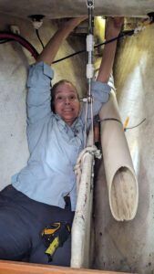
At first I thought that standing on the V-head toilet and climbing awkwardly into the chain locker was funny. I tried not to think about claustrophobia as I nestled in the portside half of the narrow space, hips wedged between the hull and a partial wall that supports our headsail stay and divides the 200 feet of chain into two balanced portions.
Then my partner John handed me the 15-ish pound windlass motor and gearbox. My job was to lift it above my head and position it correctly on the shaft protruding into the locker from the deck above. Next, I’d latch the quick coupling to lock the upper and lower pieces together. But first I had to wiggle my body around to face the bow of the boat. Splayed inside the locker, it was difficult to heft the motor above my head. And in the process, the quick coupling swung open and smacked me in the mouth, producing a fat lip instantly.
Replacing the anchor windlass was just the most recent project in the saga of our “turnkey” cruising boat.
THE NEW BOAT HONEYMOON ENDS
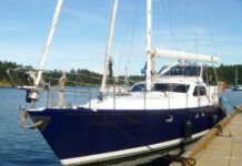
We purchased the Island Packet 40 last fall after searching high and low (and Annapolis in summer without air conditioning in my car!). It’s a 1998, one-owner, well-maintained beauty—or so we assumed. We are the first to admit that we were dazzled by the idea of having this boat and were happy to overlook most shortcomings. The only obvious thing that needed replacing was the original and non-functioning radar system, and the owner knocked off a reasonable portion of the asking price to make up for it. We were appeased.
We were so tickled to have this beautiful boat that fit our needs—my partner John is 6-ft. 3-in. so the headroom in an Island Packet is perfect—as well as our dreams for the future, that we played hooky from work one day to sail around Narragansett Bay. That’s when we realized that the radar system wasn’t the only issue we had to tackle.
That day, we ventured to Potter’s Cove on Prudence Island. John directed me to steer the boat to about 10 feet of water where he’d deploy the anchor and we’d make lunch. I did my best to keep the boat in place while he fussed with the anchor. I didn’t hear what he was saying but his body language was unmistakable. The anchor had reluctantly deployed but the windlass was an issue. Before we sat down to eat, he had determined that the mechanism needed serious work.
A NECESSARY PROJECT
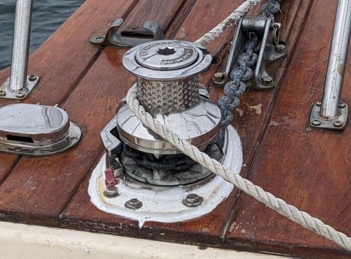
The windlass is a simple yet indispensable item on a cruising yacht. Embedded in the bow deck, it should raise and lower the anchor and chain electronically, saving sailors much aggravation and effort. An Island Packet is a heavy boat, so we carry 200 feet of chain and have a 65-pound anchor on the bow, not things we want to test our aging backs with every day. Our pre-purchase inspection of the boat proved only that the foot controls had power—the inspector wasn’t going to deploy the anchor while he reviewed the boat’s systems at the dock.
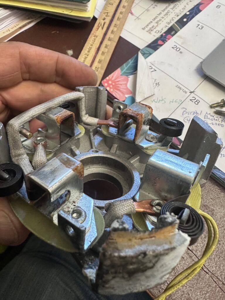
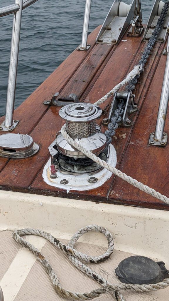
Upon closer examination, John determined the windlass hadn’t been installed correctly. It was not the original but rather a replacement windlass. The through-deck hole was cut for the original device, which was much larger (it was a Simpson Lawrence Sprint 1500, according to documents on the boat). It seemed the smaller replacement windlass was installed haphazardly: the through-deck bolts holding it on were of different lengths, and the gearbox and motor below the deck were attached with metal strapping rather than stabilized with a plate. Worse still, the poor fit meant it could not be adequately sealed to the deck, so water dripped into the motor, causing deadly corrosion.
PUTTING THE PIECES TOGETHER
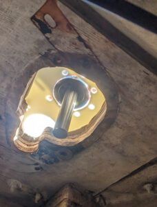
The electric motor had to be replaced but the gearbox and the stainless above-deck portion (the drum and the gypsy) could be salvaged—that was good. However, it wasn’t until days before our spring launch that John found time to reassemble the entire windlass system in a stable way that would prevent the issue of water infiltration. He had a few other projects ahead of this one, including installing a stern tower with solar panels, replacing the dead radar system, and chasing myriad wires through tiny spaces where the deck meets the hull.
Before the project could be completed, John tested his components and discovered that the original windlass shaft, which connects the on-deck portion to the below-deck motor and gearbox, was too short. The original windlass assembly was only 2.5 inches long, resulting in the jury-rigged wire strapping to hold things together below. John needed to get a longer shaft, deck spacer and longer bolts to span the 3.25-inch depth of the deck plus backing plates. Those components were not easy to find, and the parent company of Lewmar, the manufacturer, was challenging to navigate because customer service agents were not familiar with the parts he was looking for.
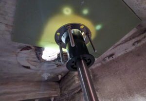
To make the windlass stable and watertight, John used resin backing plates—epoxy laminate, also known as G-10, which chewed through three jigsaw blades when cutting—both on the deck and under it, through which the windlass was bolted. He included the original circular backing plate with the new epoxy plate for extra strength. The final step was waterproofing the deck connection with caulking, Boat Life Life-Calk.
My participation in the process was simple and straightforward: I got the nuts on the ends of the bolts, then pushed that motor and gearbox assembly onto the shaft, locking it in place. And, the qualification that makes me indispensable: I fit into the anchor locker.
Tools needed:
- Hole saw to cut holes in the G-10 epoxy resin boards for the shaft and drill to make bolt holes.
- Jigsaw with extra blades to cut the G-10 backing board to fit the footprint of the drum and gypsy.
- Socket wrenches to tighten bolts from underneath when the backing plate is put in place.
Parts needed:
- Replacement motor (ordered through West Marine).
- Longer shaft and deck spacer (came with new stainless bolts, washers, and nuts long enough to secure the mechanism) from Fawcett Boat Supply, who special ordered them from Lewmar, the manufacturer.
- Resin epoxy boards cut to fit.
- Epoxy sealant Boat Life Life-Calk.
Replacement process:
- Determine if the entire windlass needs to be replaced or if just the engine has burned out.
- Examine the installation to determine what caused the engine to burn out—corrosion from water infiltration, age. Open the electric motor: if it’s corroded and rusty, water intrusion is a likely culprit.
- Remove the entire windlass assembly from the deck, disconnecting the power supply from below (shut off power supply before detaching wires). Detach the electric motor from the gearbox.
- Resin epoxy boards are available through home improvement stores. They won’t rot when mounted on the deck. Steel plates are also an option, but they require more specialized equipment to cut.
- Determine the length of the shaft and/or deck spacer necessary to connect the above-deck windlass to the motor assembly. Our Island Packet required a much longer than standard shaft and spacer due to its location on the thick teak bowsprit.
- An electric jigsaw, held by clamps to a workbench, is sufficient to cut the epoxy boards to accommodate the windlass shaft and hole for the anchor chain but have plenty of saw blades available because it’s an exceptionally hard material to cut. The board supporting the windlass on the deck can be cut to fit the mechanism’s outline to maintain an attractive appearance, the one below just needs to fit snugly against any deck contours and to have holes for the shaft/spacer and bolts.
- Test the assembly and fit before securing or applying any epoxy sealant. The shaft may include a “key” that slides into a groove and must be aligned perfectly for things to fit together.
- Assembly goes like this: put the deck level epoxy board in place at the windlass location, adding a layer of epoxy sealant where it meets the deck and where the drum/gypsy portion of the windlass sits on the epoxy board. We used double-end stud bolts (supplied by the manufacturer when the longer shaft and spacer were ordered), screwed into the underside of the drum/gypsy half of the mechanism. Slide the stainless windlass top through the hole in the backing plate, orienting correctly so chain will run from it to the bow roller. From inside the anchor locker or under the deck, slide the manufacturer’s backing plate as well as the second epoxy board up over the shaft and bolts. Secure bolts with washers and locking nuts from below. Push the motor and gearbox assembly up onto the shaft, securing with the quick connection. Caulk around the base of the windlass on the deck.
- Reconnect electrical wires.
- Test before leaving port.


