The best bilge pump in the world wont keep your boat dry if its not properly installed and maintained. While bilge pump installations are fairly straightforward-and definitely within the scope of DIY projects-there are several factors to consider (capacity, wire size, hose diameter, fuse size) before you begin, and there are some good rules of thumb to follow.
CHOOSING AN ELECTRIC BILGE PUMP
The first step is selecting the right bilge pump(s) for the job. We recommend installing two electric centrifugal pumps (preferably one with automatic water level sensor): a smaller pump mounted at the belly of the bilge to handle the incidental bilge water (rain, stuffing box drips, etc.) using minimum power and another pump mounted a few inches higher to handle bigger jobs. There are several reasons for this; the main one being that a back-up is always installed should one pump fail.
Capacity: For most mid-sized boats (30-35 feet in length), wed recommend a 1,000-1,500 gallon-per-hour (GPH) pump for the primary and one with a capacity of about 2,000 GPH for the backup. The American Bureau of Shipping recommends one 24-gallon-per-minute pump (roughly 1,440 GPH) plus one 12-GPM (720 GPH) pump for boats shorter than 65 feet.
When comparing output specs on multiple pumps, be sure the rating criteria are the same. New standards set by the American Boat and Yacht Council (ABYC) require that compliant makers rate pump capacities so that they reflect real-world usage. The ABYC stipulates that pumps be rated with a head height (also called vertical lift) of 1 meter and a hose length of 3 meters, and with a head height of 2 meters and hose length of 6 meters. Head height is the vertical height of the hose outlet above the pump outlet. Head pressure (also referred to as static head) is the resistance that a pump has to overcome when pumping water up and out of the boat. It includes the resistance generated by the vertical distance the pump has to move the water up (vertical lift) and any resistance generated by the discharge plumbing (hose kinks, ribbed hose, fittings, and bends). Some ratings also will be given at 13.6 volts, rather than the more realistic 12.2 volts (for a 12-volt system). The latter will more accurately reflect capacity in real-world conditions.
Key features: An automatic pump will rely on a water-level sensor such as a float switch to activate the pump. This can be a separate unit or one that is integral to the pump. This sensor should resist fouling and be easy to test for proper operation. Common float switches should be in a housing, otherwise they are more prone to fouling by debris in the bilge. An easy-to-access strainer (or strum box) is also important, as are long wire leads, which help keep connections out of the wet bilge area.
INSTALLATION
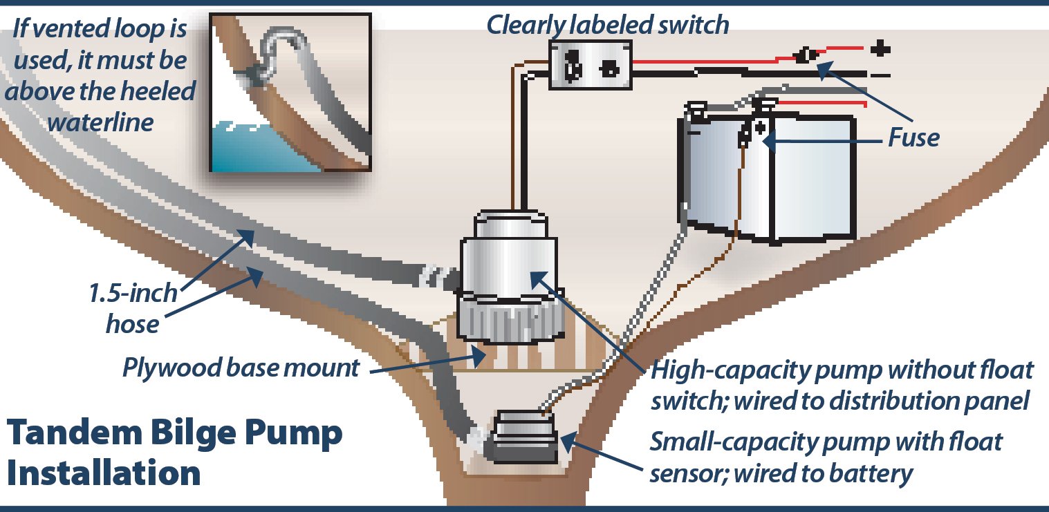
The illustration above shows one recommended setup for automatic bilge pump installation.
Location: According to the ABYC, the pump inlet must be positioned so that bilge water can be removed when the boat is in a static position and when it is at maximum heel (ABYC H-22). The mounting location also should make it easy to service the pumps and to clean them, particularly their strainers.
The discharge outlet (thru-hull) must be above the maximum angle of heel so that water outside the boat is not siphoned inside the boat. According to ABYC H22, if you can’t position the discharge this way, a vented loop (installed above the heeled waterline) and a properly installed seacock must be included in the setup. (Check-valves should not be used in this scenario.)
When installing two electric pumps, the lower-capacity pump should have a built-in float switch, be mounted at the lowest point of the bilge, and be wired straight to the battery through a fuse. The higher-capacity pump is installed a few inches higher, but not directly above the smaller pump. As the illustration shows, you can mount the larger pump to a piece of plywood thats bonded to the bilge sides. It should be wired to a dedicated breaker, which can be used as a switch, or it should also be wired to a dedicated, clearly marked toggle switch.
Plumbing: When plumbing an electric bilge pump, be sure the setup is designed to reduce head pressure as much as possible to maximize discharge capacity: use smooth hose sized to meet maker recommendations; keep hose runs as short as possible; and try to avoid bends, turns, and elbow fittings in the run. In terms of adding resistance, using a 90-degree bend in a 1-inch-diameter discharge hose is the equivalent of adding 3 feet of hose to the line, which is like a 3,000 GPH pump being reduced to a 2,000 GPH pump, if the battery is fully charged. According to pump maker ITT/Rule, small electric submersible pumps are rarely useful with more than 4 feet of vertical discharge head and medium/large submersibles are similarly ineffective with more than 7 feet of head.
The discharge line should rise steadily to the through-hull or loop. If there are any low spots in the run, water will pool there once the pump cycles off. This can create an airlock when the pump is activated again, and the pump likely will stall. Hose connections, as recommended by the ABYC, should be made with non-corrosive clamps and should be airtight.
Wiring: Use correct size wire and fuses: The proper wire size reduces voltage drop and properly fused wiring reduces risk of a locked rotor (a motor thats trying to turn, but can’t) causing an overcurrent situation and potential fire hazard.
Consult the American Wire Gauge 3% voltage drop table (www.marinco.com/page/three-percent-voltage) to be sure you’re using large enough wire. Remember that the run length given in wire-gauge tables is the sum of the positive and negative legs of the circuit; a pump 10 feet from the battery will be referenced as having a 20-foot wire run.
For the fuse size, simply go by the pump makers recommendation, and you should be set. The fuse, per ABYC standards, should be installed within 7 inches of the power source.
If the pumps leads are too short, extend them carefully. Use oversized tinned marine wire and adhesive heat-shrink connections. ABYC standards recommend using a length of water-resistant electrical cable, sealed at the pump connection, so all electrical connections can be made above the max bilge water level.
Accessories: A few accessories to consider adding to the bilge pump system include a visual/audible bilge alarm, bilge switch, and a cycle counter. ABYC standards require an alarm on boats with enclosed berths. Be sure that the alarm is loud enough to be heard over engine noise while underway and ideally by passersby or marina personnel when docked.
Automatic pumps should always be fitted with a readily accessible and clearly marked manual switch so that even if the owner isn’t around, anyone (crew, marina neighbors, or passersby) can locate and activate the switch when the need arises. Switches also should offer visual indication that the pump has power supplied to it. Our top pick for mercury-free bilge switches, reviewed in the January 2006 issue, is the electronic Water Witch 230.
If the larger-capacity pump has a float switch, we highly recommend connecting it to a bilge alarm (and alarm cut-off switch). That way, hopefully, the horn will get someones attention before the constant cycling of the pump drains your batteries. We reviewed the Aqua Vigil Alarm in the May 15, 2001 issue, and deemed it simple but quirky. We plan to revisit bilge alarms and cycle counters, including combo units like the Aqua Alarm pump monitor, alarm, and counter.
Two good references on bilge pumps and installing them are This Old Boat by Don Casey and Nigel Calder’s Boatowner’s Mechanical and Electrical Manual.
MAINTENANCE
Regular and frequent inspections of your bilge pumps are a must and should be included in the vessels overall preventative maintenance program. This helps you know when to replace worn or damaged components (bad float switches, deteriorated hoses) before they fail. Before you set sail, its always a good idea to make sure the pump has power and is working properly, keeping in mind that testing should verify the actual pumping of water overboard, rather than (in the case of electric pumps) simply switching the pump on and listening for motor operation.
Keeping your bilge clean can be a hassle, but it doesn’t compare to the headache of a locked rotor or an impotent bilge pump in an emergency.
For more details on specific pumps, check out our most recent tests of high capacity bilge pumps of greater than 1,500 GPH.
For more comprehensive guidance in carrying out an upgrade of your boats essential systems, check out our 5-volume ebook series on Marine Electrical Systems at https://www.practical-sailor.com/products.
This article first ran in Practical Sailor on February 21, 2021













From bitter experience on my Olsen 34 the pump discharge point should be well above the water line. On the Olsen 34 they put the discharge on the port side at the stern. Even though there was a loop, when the boat was heeled on a starboard tack the discharge went under water and slowly back flowed thru the discharge line. Adding a check is one idea but they create a lot of pressure loss and a debris trap that can plug the line just when you need it the most. Better idea is to put the sump discharge point on the center line well above the water level when heeled.
I am a marine technician and am frequently dealing with bilge pump failures. I agree with most of the comments made here. I personally do not like bilge pumps with internal float switches. They are more convenient to install, but how do you test them? I like to be able to physically lift the float switch to test the pump system. This cannot be done with internal float switches. Some, but not all bilge pumps with internal float switches have a button for testing…. does anyone know how these work…. what are these really testing???
Second comment…. the electrical connection adjacent the pump. I like to use a 4 circuit terminal block to connect the seven wires ( bilge pump(2), float switch (2), manual +ve, auto +ve, and ground) together. This should be mounted as high as possible. And do not forget heat shrink on all connectors. This makes troubleshooting with a multi meter so much easier when something goes wrong. Cutting into heat shrunk butt connectors is time consuming and requires repairing after the troubleshooting is complete.
For boats with a deep bilge, the best option is a diaphragm pump located above the bilge and wired to a float switch. Better yet are two! An event counter and an audible alarm or beeping device is critically important. It should be audible when motoring or under sail. I use a “truck backing up beeper” wired in the circuit. An additional high water siren on a separate float switch completes the setup.
I’m a ~25 year fan of a dry bilge using a whale gulper pump with a water witch sensor. I’ve mounted the sensor face down against the bottom so it senses at minimal water. The ability of this diaphragm pump to suck water and air, or both, and the 15s off-delay provided by the water witch ensures it will scavenge the bilge dry. A few inches higher I use a Rule 3700 vane pump. I refer to this as the crash pump, and I’ve drilled a 1/8” hole in the discharge hose next to the pump outlet to prevent a fatal airlock. I’ve always had pump cycle counters and an alarm if the crash pump ever runs for 15s. And it’s connected to my on board security system that’s monitored by a central station thru a cellular connection. The security system also reports low voltage. (Hello? Most boats that sink do so at the dock, often with no one nearby.) I always check and reset the counters first thing in the morning or when I arrive at the boat. And I always test the system at annual launch. Overkill? No such thing. More recently I added a Legend PVC T-655 ball check valve in the whale pickup hose because I got tired of changing its duck bill valve. With this config the odds of a failure before it’s too late are almost nil. I think ABYC standards are inadequate—the first task is to keep the water out. Hope that helps.
A good article, but I do notice that PS articles sometimes reference material from many years ago, ala “…reviewed in the January 2006 issue, is the…”. I have seen several references in various articles and wonder if the technology has changed, or other standards have changed since some of these original reviews? Thoughts?
Good article. However, seems a little disconcerrting
A 2” hole 3’ under the waterline will allow 8,340 gal. of water/hr to enter your boat, regardless of how many bells and whistles you’ve added to your system. Bilge pumps are adequate for nuisance water, nothing more. You better have plans for plugging holes and an EPIRB handy for anything else. Just my opinion.
The article recommends using a manual switch for the high capacity pump. An alternative is to install an automatic switch, placed high enough in the bilge so that it will not trigger in ordinary circumstances. Wiring in an audible alarm will alert you to high water. If it is loud enough, it could attract attention from others at your dock or mooring field.
I disagree with the recommendation in this article to have the automatic bilge pump deep in the bilge and the manual higher up. I had an automatic bilge pump get stuck on and run the battery dead several times. I think switch failures in those pumps happen often enough that I don’t want the automatic as the primary. Incidental rain water etc. is easy to remove by switching on the manual pump. You want the automatic for times when water is coming in unexpectedly while you are not below to notice it. I have had that happen several times, and the primary in the bilge handled it just fine once switched on. I am not even sure I would want the backup automatic because that might have allowed me to miss the water accumulation. You don’t hear the pump if the engine is running. As John noted, if you have a serious hole, these pumps are not going to keep the boat from sinking.
If the pump intake is in the bilge on centerline and the boat is severely heeled like in knockdown (a sister ship sank from knockdown on a lake) and water has poured thru the companionway, the water inside is all on one side and may not reach the pump intake on centerline. So? Two pumps, one each side? Overkill? Enough battery power to move that much water? The first task is stop the ingress of water, get companionway closed and get boat at least partly upright. Assuming one manages to get boat upright, whether fixed keel or swing keel trailer sailer, there is still a massive amount of water has to get pumped out fast. A 2000 GPH pump is only 30 gpminute, actually less. Two of them 60 gal per minute.
Also, at some point aren’t batteries going to be submerged and short out? Or just run down from high demand from pumps?
So: location of intake hose(s) at severe heel? GPH? Battery short out or rundown? Overkill?
On my endurance 44, for offshore, I used a decent sized electric pump with check valve, a counter, and a separate high level audible alarm, two feet higher than the regular pump float switch/alarm.
I also carried a separate gasoline powered pump with 1 1/2” hoses complete with strainer and fire hose connection available. It sucker a lot of water and with the firehose connector, could be used to fight fire and would shoot water about 50’ effectively. The hoses were long enough to put the pump on deck and to be primed from there. This is a good water evacuation plan in an emergency if tested regularly. I had a 2.7 hp kubota lightweight setup. Inexpensive and very effective. After that, it was a 20 litre bucket!
I have a 1990 Alden 44 with a deep narrow bilge filled with a centerboard hydraulic slave cylinder and have been using a diaphragm pump as Bob described above. I always found the Achillies heel to be the float switch which was bulky and typically failed in one to two years. I have since changed to a water pressure switch. The cup is placed in the bottom of the bilge on a 1/2″ square piece of starboard connected to a vertical PVC tube, held in place by a hose clamp. All the mechanical parts are mounted just under the floorboards where they stay safe and dry. I can clean the cup by loosening the hose clamp and lifting it out. This solution has been working great for me for 6+ years without a failure.
After dealing with faulty water sensor on my Rule bilge pump that drained my battery, i plan to change over to a diaphragm pump with an external sensor/switch that can be properly cleaned or replaced, any recommendations?
Ric,
interesting. I have just done the opposite. we had the DIAPHRAGM pump high in the bilge with a pickup tube to the lowest point along with a WaterWitch 100 series mounted at the very bottom, to keep the bilge dry. had this set up for 10+ years. then the pump(s) kept losing prime once we became much more active cruisers. constantly battling as to why over a period of 5-6 years. replacing pumps. dealing with possible air leaks in the strainers. contamination in the rubber flappers in the pumps themselves, which I was told by Jabsco are extremely sensitive.
We have found diaphragm pumps difficult to maintain, and ironically easily lose prime when they are supposed to be self-priming. the Centrifugal pump, although not self-priming are more reliable since they prime in the presence of water. which is the only time you want them primed.
A few weeks ago I ripped all that out and went with a Rule 500 GPH electronic water sensing CENTRIFUGAL pump. no more wire mesh external strainer to constantly clean. mysterious losses of prime. extra plumbing fittings etc.
Yes, the Rule 500 GPH comes on for 1 sec every 2.5 mins to check for water, but I never hear it (wife does but I can turn it off at night). Its wired to an activity light which is nice to notice when it blips on. that confirms its operating which I like.
my 2,700 GPH Rule crash pump has a WaterWitch 230 and an alarm if it comes on.
I appreciate the reminders in these comments that bilge pumps are only good for small leaks that might sink your boat.
a Crash Pumps just buys a little time if its a big leak.
Eddie
The pressure switch that I have been using which I referenced above is a Groco AS-100. The pump I use is a Jabsco par max 4 diaphragm pump.
The Jabsco is a 31705-0092.
On passage recently our 5 yr old Water Witch sensor fired off our 11year old Rule 2000gph with an audible alarm. It’s so long since we installed and its never fired off the we were unsure what it was! Of course we test regularly, but it was a surprise just the same. This may be testement to a very dry boat, but also an indicator that both the pump and switch have lasted the test of time. It was a leaking raw water pump in the engine bay after a 12hr motoring run.
I would like to install a secondary bilge pump with an automatic switch so when I more my boat and we get a lot of rain I don’t need to worry about having to use my manual bilge pump
If I route my outlet line into my manual outlet line do I need a check valve in one of the water lines
How do you install bilge pumps in a shallow draft 40′ sailing catamaran when there is only a few inches of bilge below the flooring/soles? I would like three in each hull – 0″, 6″, & in engine compartment – plus manual pumps. The engine compartments should be ok and the manual pumps can be mounted higher, between the bottom strainer (strumboxes?) and the thru hull. Can automatic electric pumps be mounted above the LWL with a reinforced hose leading to a strumbox under the floor?
Answering my own question. After several days of research, I discovered the Rule LoPro (Low Profile) 900 GPH pump. Its installation manual even has a chart showing the flow/head curves at 12vDC for each of the three hose size options.
Regarding the question asked above, about how to test automatic bilge pumps (those with internal switches): most of these small pumps have a test knob that has no other function than to allow the user to rotate the float shaft, just as it would rotate if the water level were rising; thus both the movement of the float itself and the movement of the switch plus motor assembly can be tested.
Good winds and lots of water under the keel!
I agree with John Russnogle’s above post. Bilge pump(S) are likely unable to cope with a major hull breach, or even a dropped shaft. If the water ingress cannot be slowed at the source, a life raft might be the best back up if offshore. For power boats, there is yet another emergency option. I have installed commercially made diverter valves at the raw water strainers, with large diameter hoses positioned to pull engine cooling water directly from the bilge. Heaven forbid that I ever need to test the capacity of this arrangement, but I have no doubt that twin 315 hp diesel pumps will beat my three electric bilge pumps.
Very informative article but one other factor should be taken into account in my view. Non live-aboard boats are usually left unattended at a mooring far longer than they are with someone aboard. If a leak develops the pump will keep pumping until the battery dies. All else being equal, a more efficient pump would discharge more total water than a less efficient pump until that happens. One way efficiency can be estimated is by calculating gallons flow per amp draw. There should be a column in bilge pump comparison articles showing gal/amp. That’s the basis I used to select an additional emergency 2000 gal/hr bilge pump with WaterWitch switch for my Beneteau 44.7 that came from the factory with manually switched bilge pumps with about 350 gal/hr total capacity!
So far the new pump has not had to run in anger but I’m confident if it does it will pump the most gallons of water for as long as the batteries last. Hopefully that may be long enough for someone to notice and take action or call me.
Simon Zorovich
PoleStar
Staten Island, NY
I’m refurbing a 27′ elderly grp sailboat with a deep bilge in the rear part of the encapsulated keel, and I need to spec and install at least two electric bilge pumps – large and small. The pros and cons here of auto-sensing are interesting.
I learned long ago the habit of using a manual pump on joining a boat, then twice a day, counting and logging the ‘full’ strokes to assess whether anything had changed. What does the hive mind think?