When the technical management team of the Volvo Ocean Race (of which I am a member) started looking at upgrading the performance of boats for the 2005-2006 race around the world, we considered a number of options, including bigger versions of the 60-foot water-ballasted boats used for the 2001-2002 race, big multihulls, and higher-performance monohulls. Volvo finally chose a can’ting-ballast, multiple-foil 70-foot monohull with a limited amount of water ballast to adjust fore and aft trim when running downwind at high speeds in the huge seas of the Southern Ocean.
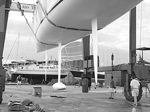
Accepting can’ting ballast keels was a big step. These keels offer the possibility of big increases in performance, but there’s no free lunch. A can’ting ballast keel introduces significant engineering complexity and cost increases compared to a conventional fixed-ballast keel. Multiple movable appendages create potential structural weaknesses, not only in the appendages themselves, but in their support structures.
For Volvo—a company whose name is almost synonymous with safety and conservatism—adopting leading-edge technology for a class of ocean racers designed to operate at top speed in every conceivable condition was more than a leap of faith. The choice to pursue a can’ting ballast keel boat was a carefully considered decision to look to the future of performance monohull sailing. And when you look to the future, you see can’ting ballast keels staring you in the face.
The idea of the can’ting ballast keel has been around for a long time. One version of the modern can’ting keel—the patented CBTF (Canting Ballast-Twin Foil) dates back to the late 1980s, and is the direct descendant of the late Tom Blackaller’s “geek” 12-meter, built for the 1987 America’s Cup in Australia. The geek had a fixed bulb keel and a forward canard appendage, but the hydrodynamic groundwork was laid for the logical next step—a can’ting ballast keel with rudders both forward and aft of the keel.
You really have to change your mindset about sailboat design when you consider can’ting ballast boats. In the conventional fin-keel sailboat, the keel serves two functions: to contain the ballast that provides the righting moment necessary to keep the boat rightside up, and to provide an efficient lateral plane that stops the boat from sliding sideways when the force of the wind fills the sails, especially when sailing upwind. Dead downwind, the conventional keel sort of gets in the way, creating drag. Upwind, the keel creates a combination of righting moment, lift, and drag.
The can’ting ballast keel, however, cannot provide efficient lateral plane for upwind sailing. The keel fin or strut is no larger than is absolutely necessary to support the ballast bulb. When the ballast is can’ted to one side, the strut is largely ineffective in providing lateral plane. With a can’ting ballast boat, appendages other than the keel must provide the lateral resistance that both balances the driving forces of the sails, and allows you to steer the boat. A can’ting ballast keel boat, without its other appendages, would pretty much slide sideways through the water.
Here, the two most common approaches to can’ting ballast diverge. With the patented CBTF approach, centerline rudders fore and aft of the ballast package steer the boat, balance the helm, and provide the necessary lateral plane. The fore and aft rudders can operate together or individually, with different angles of attack. This creates an extremely efficient lateral plane, significantly reducing leeway when sailing upwind.
The other approach uses single or twin rudders at the aft end of the boat, and single or twin daggerboards forward of the ballast package for lateral plane and balance. With twin daggerboards and/or rudders, these appendages are angled from the perpendicular so that with the boat heeled at its optimal sailing angle, the leeward appendages are perpendicular to the surface of the water, and therefore most efficient at preventing leeway.
The downside with twin rudders and twin boards is the additional weight of a second pair of foils. The upside is a slight gain in engineering and construction simplicity compared to forward and aft rudders, particularly if only single centerline rudders and boards are used.
Open 60 monohulls often use the twin aft rudder, twin forward daggerboard approach, since rules for major events for these boats limit the static heel angle of the boats, with the ballast fully can’ted, to a mere 10 degrees. The Volvo 70 class and the new super-maxi “maxZ86” class on the other hand, control not the heel angle of the boat, but the can’ting angle of the ballast package. By allowing a greater can’ting angle—40 degrees in the case of the Volvo 70—the relatively small ballast package is far more efficient in keeping the boats upright, making them extremely powerful, particularly when reaching.
The static heel angle for a Volvo 70, with the ballast fully can’ted, will probably be greater than 25 degrees, perhaps making centerline, perpendicular appendages a reasonable alternative to reduce drag and weight. We fully expect, however, to see various configurations as different designers come to grips with the problem of designing a boat with minimal performance weaknesses, whether upwind, reaching, or running.
So far, the application of can’ting ballast keels has been primarily to ocean racing boats. Notable examples are open-class monohulls, such as the Open 60, the tiny Mini 6.5 class (about 21 ft. overall), the new Volvo 70, and the maxZ86 class.
The Schock 40, a successor to the DynaYacht Red Hornet, campaigned by Peter Isler starting in the late ’90s, is the first production racer/cruiser with a can’ting keel, and has been a pioneering boat in promoting the can’ting ballast concept.
There have also been several high-end state-of-the-art cruising boats designed with combination can’ting/lifting keels. This would be the ultimate combination for a cruising boat, which could extend the keel for maximum righting moment when sailing in the ocean, but reduce draft for coastwise cruising and shallow anchorages.
Big cruising boats fight a constant battle with weight and draft. Cruising amenities are heavy, and deep draft eliminates desirable cruising grounds. It is very difficult to create a big cruising sailboat with enough ballast-generated stability to sail upwind efficiently. The can’ting, retracting ballast keel can offer the best of both worlds in creating a high-performance cruising boat for the owner with deep pockets.
How They Work
The basic principle is pretty simple. A streamlined bulb of lead is fitted at the bottom of a slender, air-foil shaped strut machined from high-strength steel, such as 17-4PH alloy. This alloy is not as corrosion-resistant as more commonly used steels such as type 316 stainless, but it is considerably stronger. High-strength, off-the-shelf sailboat hardware components such as snap shackles and padeyes are often made of 17-4PH steel, so it is not a particularly exotic material.
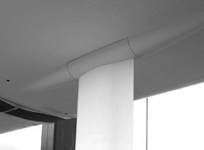
Just inside the hull surface, a longitudinal pivot bearing provides the axis of rotation of the keel fin. The keel strut itself extends up into the hull, where a mechanism—generally a big hydraulic ram—applies force to the top of the keel fin to push it to one side. The fin rotates about its pivot point, and the ballast bulb and the lower part of the fin are pushed or pulled to one side or the other. Think of it as a big, heavy pendulum that can be moved from side to side and fixed in any position to offset the heeling moment of the pressure of wind on the sails. The boat can be sailed flatter and faster.
Structure and Safety
This sounds pretty simple, but the forces involved are huge. Substantial structure is required inside the boat to support the weight of the keel and can’ting mechanism, and the entire package has to be strong enough to withstand shock. The bulb has to remain attached to the fin, the fin has to stay attached to the can’ting mechanism, the can’ting mechanism has to stay attached to the boat, and the whole shebang has to be able to absorb the impact of grounding or collision with floating debris without tearing the boat apart.
Another engineering complexity is designing a means of sealing the point at which the movable keel strut penetrates the hull. This is one of the more proprietary sections of the design of can’ting ballast systems. Sealing the entire can’ting mechanism inside a watertight compartment in the boat is one solution, but the better solution is to prevent any water from getting into the boat in the first place by the use of a series of engineering-tolerance seals. This is not a trivial exercise.
In addition, a substantial number of safety features need to be incorporated into the system. For a Volvo 70, two separate can’ting mechanisms are required, just in case one system fails. Each system has to be engineered to the same specifications, so that they are truly redundant.
In addition, we will replicate a worst-case scenario—rig out of the boat, no power to operate the hydraulics, and the boat upside down—and require three of the crew to right the boat from full inversion from inside the boat, using only manual means such as a hand hydraulic pump to operate the can’ting mechanism and get the boat rightside up.
Needless to say, these full inversion tests will generate a lot of interest on the part of the sailing public.
Normally, a can’ting mechanism is driven by a power-operated hydraulic pump. Only hydraulics can effectively generate the type of mechanical advantage required. The hydraulic pump can either be driven directly via a power take-off on a generator or main engine, or, less efficiently, by an electric motor.
In the event of total power failure, a manual hydraulic pump—you’ll be familiar with these if you have a hydraulic vang or backstay on your boat—can drive the system, although it will take a lot longer to can’t the keel than with a powered system.
Each can’ting mechanism has to be capable of holding the ballast keel at any angle. You don’t just drive the keel out to one side and lock it off— you have to be able to hold it anyplace between vertical and fully can’ted.
Then there’s another little safety consideration: Sailing with the keel all the way out to the windward side, your resistance to capsize is very high in one direction, very low in the other. This is not a real problem in upwind sailing, because you want all the righting moment you can get on the windward side. Anyone who has ever sat on the windward rail during a race knows what this is all about.
Downwind sailing is a little trickier. A jibe and a round-down broach could catch you with the keel can’ted to the wrong side of the boat, and lay her flat in the water.
The Volvo 70s—and all other big boats with can’ting keels we have looked at—have a panic button which can almost instantly dump the keel back to the boat’s centerline, where it will then behave like a conventional ballast keel. This is much like the release valve on a common hydraulic jack, which essentially opens flow within the system, allowing it to return to equilibrium. With the keel on centerline, the boat behaves much like a conventional boat with a fixed keel, albeit with less ballast.
Another serious safety consideration is the vulnerability of forward foils to damage from floating objects. Generally, forward foils—whether daggerboards or rudders—are deep, high-aspect ratio fins, often almost as deep as the keel itself.
Compared to a conventional fixed fin keel and aft rudder combination, there is much more risk of damage associated with a forward foil. Generally, forward rudders are designed to shear off without compromising the watertight integrity of the hull, as are forward daggerboards. If you lose a forward foil, however, your ability to steer and balance the boat effectively will be significantly compromised.
For a can’ting ballast cruising boat, this problem probably leads more in the design direction of a forward daggerboard, rather than a forward rudder. A daggerboard that merely slides up and down may be easier to design with collision safety features than a more complex rudder assembly.
Weight Savings
On most racing boats, the ballast keel is the single heaviest object on the boat, and makes up a large percentage of the total weight. On a performance cruising boat, the ballast keel might constitute about 40% of the weight of the boat. As an example, the 18,250-pound J/133—a modern 43-foot cruiser/racer—has a keel weighing 7,250 pounds.
On an extreme keelboat—the 80-foot America’s Cup Class is one of the most extreme examples of ballast/displacement ratio sailing today—the ballast bulb (no fin, just the bulb) might contain more than 47,000 pounds of lead out of a total weight of just over 55,000 pounds for the complete boat.
While both the angle to which the bulb can be can’ted and the length of the keel strut help determine the righting moment of a can’ting-ballast boat, a boat such as the Volvo 70 requires only about half the ballast weight with a can’ting keel as it would need in a fixed keel of the same draft to achieve the similar righting moment.
This weight savings increases the sail area to displacement ratio dramatically. A minimum displacement, minimum keel weight Volvo 70 goes about 27,600 pounds, and has a bulb weighing just over 9,900 pounds. The same boat with a fixed keel would need to weigh over 37,500 pounds, and have almost 20,000 pounds of ballast. It’s not rocket science to figure out that most of the time, the 27,000 pound boat is going to take a lot less horsepower to drive to a given speed than the 37,000 pound boat. Taken another way, for the same amount of sail area (horsepower), the lighter boat is going to be a lot quicker.
Remember, boats of this type are planing boats, so the theoretical top speed of a conventional displacement boat—about 1.34 times the square root of the waterline length in feet—simply doesn’t apply. A can’ting keel helps boats achieve higher performance by reducing total weight for a given righting moment.
Just as in racing cars, reducing weight means more speed for a given amount of horsepower.
The higher sail area to displacement ratio is particularly important in offwind sailing. Upwind, a boat’s stability will determine whether or not any more applied horsepower will produce more speed. Downwind, it ain’t necessarily so. Stability is less critical when there is little heeling moment applied to the boat, so the extra horsepower downwind can be more easily converted into speed.
Of course, the can’ting system itself adds a lot of weight to the boat. The part of the keel fin above the pivot point adds nothing to performance, but is essential to provide the lever arm to push the ballast to one side. The shorter that lever can be, the less useless weight there is inside the boat.
But a short lever arm means that more force must be applied to push the ballast to one side, just as the short arm on a see-saw requires a heavier person to achieve equilibrium with the lighter person at the end of the longer lever on the other side of the fulcrum.
The powerful hydraulics required to drive the short keel arm are heavy, and heavily loaded. Much of the development in can’ting keel mechanisms is geared towards saving weight inside the boat by shortening the upper keel lever and employing lighter, stronger, faster hydraulic systems.
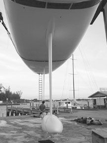
This type of development is not cheap, and is highly proprietary. You will not find close-up pictures of the can’ting mechanisms of boats in the maxZ86 class and the new Volvo 70s plastered all over the sailing magazines, at least not for a while.
All we can say is that if you go on an absolutely state-of-the art can’ting keel boat, there is nothing obviously different about the inside of the boat. You will not find a massive internal structure and huge amounts of machinery intruding into the interior spaces. The entire mechanism is compact enough to fit under the floorboards, and the essential structure to support the keel and can’ting mechanism is fully integrated into the yacht’s normal structure.
This means that a can’ting keel could be incorporated into a high-performance cruising boat without compromising the space available for accommodations. Of course, you’d want to keep those accommodations as light as possible to take full advantage of the possible weight savings.
Canting keel mechanisms may be developed past infancy, but they are just barely reaching the stage of adolescence. They have reached the stage where design details are moving forward at rapid speed, just as in the development of computers. Today’s state-of-the-art may be tomorrow’s ho-hum.
Cost
No one is going to claim that a can’ting keel boat is as cheap to build as a fixed-keel boat. There are a variety of can’ting mechanisms around—many protected by patents—but they are not exactly off-the-shelf items that you buy out of a marine catalog. For most of us, this means sitting on the sidelines and watching the big boys play, at least for now.
The Schock 40, however, is similar in price to other, more conventional racing boats of her size, so the time is not far off when can’ting keel boats will seem less like exotic, expensive toys, and more like mainstream options.
We can hardly wait.
You can learn more about patented CBTF technology on the internet at www.dynayacht.com. For information on the Volvo 70s, go to www.volvooceanrace.org. For information about other types of can’ting ballast boats and systems, enter “can’ting ballast keels” in an Internet search engine.








Great article, thanks Darrell
As you say, the developments made were to make everything within the boat more compact and lighter. Were the very early models of the 1990’s in this regard over-engineered and therefore relatively safe, even if using a manual rope & winch system ?
Thanks