Stepping up to 24 VDC
Page 4
Stepping up to 24 V DC
Weve been witnessing an increasing trend of new boats in the 40- to 60-foot range being manufactured with dual-voltage electrical systems (12 VDC and 24 VDC). So we called the electrical engineering departments at a few high-end boat manufacturers to find out about the driving force behind outfitting vessels with 24VDC electrical systems.
The boatbuilders told us that the 12VDC electrical loads on new custom and semi-custom boats over 40-foot boats are staggering. Electric windlasses, electric bow thrusters, electric winches, underwater hull lights, and DC power inverters-these are just some of the must-haves on todays pocket yachts. Unfortunately for the electrical engineers who are designing the distribution systems for these new niche vessels, most of the high-amperage loads are located at opposite ends of the vessel, far away from the vessels battery banks.
Although most high-amperage accessories operate for only brief periods of time (bow thruster, windlass), they still require upwards of several hundred amps when operated at 12VDC. Because the cable runs to a bow thruster (high amperage load) are typically long, and we are only starting out with 12 volts, very large diameter power cables are required to keep the voltage to the thruster from dropping more than 10% when the thruster is under load.
Large-diameter cables mean more copper, and more copper means more weight. The last thing a boatbuilder wants to do after having gone through all the expense of using E-glass balsa-cored composite materials or carbon fiber to make their boat lighter, faster and more efficient is to have their own electrical department load down the boat with hundreds of feet of heavy cooper wire. The solution is to increase DC system voltage, which reduces the amperage requirements of the DC accessories. With amperage requirements lessened, smaller diameter (lighter) power cable can be installed. This in turn will help the vessel hit its performance numbers.
This sounds like a lot of trouble to save a couple of hundred pounds of weight on a 40-foot vessel, but when you move up into the 60-to 80-foot range, the weight saving averages around 35 to 40 percent.
For more information on marine batteries and other electrical systems, purchase Marine Electrical Systems, Volume 3, Panels, Monitors, Charging from Practical Sailor.
Or, buy the entire Marine Electrical Systems five-part series!
Breaker Panel Installations – DIY Tips From the Pros
Page 7
DIY Installation Tips From the Pros
We made some calls to a few well-respected boat yards and asked their electricians what problems they have experienced with customer-installed (DIY) breaker panel installations.
Almost all of the electricians said that there is usually not enough wire length left behind the panel to comfort- ably (and safely) remove the panel for service. Another problem: The accessory panels are being installed in spaces that do not have sufficient depth to accommodate the panel and the radius of the primary feeder wire. The pros indicated that this squashing usually loosens the feeder attachment point and causes all sorts of intermit- tent voltage problems.
We were reminded of the importance to mark and identify your wires before you remove the old distribution panel. Mark the individual accessory wire with a number, and if you can get your hands on the jacketing of the two core wire as it enters the electrical panel, print right on the wire with a fine point permanent marker the wires identification name (stern light, radar, etc.). A few of the electronics dealers we spoke with mark their distribution wires with a portable label-making machine, made specifically for marking wires. This wire-marking system prints out clear wire tags that wrap around the wire, much like a clear Band-aid.
Another area of concern is the soldering of crimp terminals onto the distribution wires. We were told about several DC panel installations that looked absolutely perfect at first glance. The wires were well marked, well organized into bundles, and stitched up with wire spiral wrap. The only problem was that all of the lug connections to the individual circuit breakers were soldered, but not crimped. Solder melts at a low temperature and therefore is convenient to work with on copper wires. But when wires heat up from overcurrent or an electrical short, the solder will melt and the electrical terminal will fail. (The approximate melting temperature of 60/40 solder is 360 degrees Fahr- enheit). Always crimp your terminal lugs. You can add solder to finish up a lug, but the physical crimp is how the lug was designed to be attached to the wire.
For more information on marine batteries and other electrical systems, purchase Marine Electrical Systems, Volume 3, Panels, Monitors, Charging from Practical Sailor.
Or, buy the entire Marine Electrical Systems five-part series!
Inverter-Charger Terminology – What Does All That Mumbo-Jumbo Mean Anyway?
Page 16
What Does All that Mumbo-Jumbo Mean Anyway?
Established industry standards enable consumers to know what exactly it is theyre buying. They set a benchmark for product quality, performance, and safety, allowing consumers a point of comparison. Compliance, certification or third-party testing are not required, but in the case of inverter-chargers, if a manufacturer can honestly claim that this has been done, it gives them a leg up on their competitors, in our opinion.
However, this is a tricky area, and rest assured, manufacturers play games with it. To help readers decipher the related alphabet soup, we offer this roundup of the terminology often used with inverter-chargers.
[pick up UL, ETL, CSA and CA logos from websites]
? UL: Underwriters laboratories. A nationally recognized, in- dependent, nonprofit organization that writes standards and tests products for safety certification. (www.ul.com, ulstandardsinfonet.ul.com/)
ETL: originally ETL Testing laboratories, now Intertek Testing Services. A nationally recognized third-party product safety test lab. (www.intertek.com)
ISO: International organization for Standardization. The worlds largest developer and publisher of international product standards, ISO is a network of standards groups in 163 countries. (www.iso.org)
CSA: Canadian Standards Association. A nationally recognized and fully accepted, nonprofit standards group on a par with the UL or ETL. (www.csa.ca)
CE: The CE mark is the makers declaration that the product conforms to all applicable European Union standards. Any manufacturer can self- certify its products to CE.
ABYC: American Boat and Yacht Council. Develops safety standards for the design, construction, equipage, maintenance, and repair of small craft and their systems. ABYC Standard A-31 relates to inverter-chargers. (www.abycinc.org)
Listed or Certified to: These words imply either third- party testing of equipment to ensure compliance with industry-recognized and accepted performance and safety standards, or in the case of European products a manufacturer declaration of conformity to some pretty strict ISO Standards. These products often carry the logo of the certifying group, like those shown here for UL, ETL, and CSA listed products.
Designed to comply with: This is nothing more than the makers good word that on the drawing board, things looked great, but there is no assurance that the product actually com- plies with industry standards.
For more information on marine batteries and other electrical systems, purchase Marine Electrical Systems, Volume 3, Panels, Monitors, Charging from Practical Sailor.
Or, buy the entire Marine Electrical Systems five-part series!
Wind Generators 101
Page 4
WIND GENERATOR 101
Wind turbines convert the kinetic energy of the wind into mechanical power, and ultimately electricity. This electricity can be used immediately to power equipment, but is typically stored in batteries for future use. Larger turbines may generate enough power to carry or float larger loads (such as a small fridge during an overnight stay aboard), while smaller units produce enough electricity to power smaller loads for a few minutes (bilge pumps, etc.) or perhaps top off your battery banks after a weekend outing.
All generators share a few basic components: a rotor-they don't propel, so theyre not propellers-with aerodynamic blades, an electrical generator, some form of rotor over-speed control, and a mounting system (pole, arch, etc.). Most also will have rotating electrical contacts, which enable the unit to operate in a continuous 360 degrees of rotation. All but one of the units in our test, the KISS, had this feature. The KISS generator has an internal spring (inside the mount) and a rope lanyard tied to the tail of the unit and mounting pole-the lanyard is a specific length to prevent the unit from rotating more than three or so times, after which the spring is supposed to return it to its original position once the wind dies down.
Wind turbines either produce direct current (DC) or alternating current (AC) power, which is then converted to DC via a rectifier. Of the models we tested, the KISS and both Ampair units utilize a rectifier to convert AC to DC, while the Rutland 913, Air Breeze, and Superwind 350 produce DC. Each approach has its pros and cons: AC can be transmitted over longer wire runs with less power loss (due to overall resistance of system wiring), even when smaller gauge wire is utilized. DC systems, on the other hand, don't require the use of a rectifier, which reduces expense, cuts down on the number of parts that might fail, and eliminates a few installation steps. As for cons, DC motors have brushes and commutators, both of which require periodic maintenance to prevent generation of electromagnetic interference (EMI), which can disrupt onboard electronics. The rectifying diodes in AC-producing units can also be damaged if exposed to reverse-polarity voltages during installation or maintenance.
For more information on wind power generation, purchase Marine Electrical Systems, Volume 4, Alternative Energy.
Or, buy the entire Marine Electrical Systems five-part series!
Choosing Solar Panels for Your Boat
Page 17
SOLAR POWER
In simple terms, and leaving out the quantum nature of light, solar panels work by converting the energy in sunlight (or any light) to an electric current. The sunlight striking the silicon material in the panel causes the material to give up electrons, which then can be used to power something, or for storage in a battery. The amount of power potentially available from the panel is related to the light intensity, the angle of the light to the panel, the panels temperature, and the cell material.
LIGHT INTENSITY. The greater the amount of light falling on the panel, the more power available from the panel. The output of a panel is comprised of two measurable quantities, voltage and current. While solar panel voltages are fairly insensitive to light levels, the output current will double for each doubling of the light intensity. Since power is the product of voltage times current (P = V x I), and since the voltage is pretty constant, the power output is directly proportional to the current. Monitoring the current will be a close analog of the panels output power.
ANGLE. The angle of the solar panel to the sun will have a fairly large impact on the panels power output. For the best results, the light should hit the panel perpendicularly to its surface. As the suns angle moves away from perpendicular, the light intensity falls off as the cosine of the angle. One simple way to demonstrate this effect is with a pad of paper and a desk lamp. Hold the pad so that its surface is perpendicular to the light and then notice the size of the pads shadow. Now, change the pads angle away from perpendicular and watch the effect on the
shadow. At increasing angles, the shadow will get smaller. The smaller the shadow, the less light hitting the pad (solar panel). Additionally, below a certain angle, the sunlight will just reflect off the panels surface without producing electricity.
TEMPERATURE. The silicon material used in the production of the solar panels is sensitive to variations in temperature. As the panel temperature increases, the power output goes down. As a rule of thumb, the power output goes down 0.5%/C (or about 1%/F). The panels, since they are absorbing solar energy, will be warmer than the surrounding air. Therefore, air temperature will not be a good indicator of panel temperature. Also, some panel ratings are given at 20C (68F). Hence, on a warm summer day of 90F, and ignoring the increase in the panels temperature due to solar absorption, the output power will be about 20% less than the rated power.
CELL MATERIAL. Solar panels fall into three distinct groupings: monocrystalline, polycrystalline, and amorphous.
For more information on Solar Power, as well as readers real-world experiences with panels from various manufacturers, purchase Marine Electrical Systems, Volume 4, Alternative Energy.
Or, buy the entire Marine Electrical Systems five-part series!
Three Common Errors Made With Boat Electrical Systems
Page 7
Three Common Errors Made in Boat Electrical Systems
Boats with AC power systems continue to give their owners problems. Many of these problems are avoidable, and some are deadly. The major problem in using power from shore is that the risk of lethal shock is substantially greater in and around a boat than it is in a house. Moreover, the nature of the shock hazard changes when the boat is moved from freshwater into saltwater.
An AC electrical system must be designed and installed on the boat in such a way that the crew and any nearby swimmers are protected, no matter what kind of water is underneath your hull. Any stray current in the system will always work its way back to the source of power. And when you tie into shore power, its going to head for the AC ground that is established somewhere up on shore, possibly hundreds of feet away. The return point for shorepower is a conductive rod driven into the earth. All leaking current heads for the driven rod.
When it comes to shorepower systems, its a serious mistake to treat a boat like a floating house. The electrical standards established by the American Boat and Yacht Council (ABYC) clearly indicate that you should handle the entire boat as a grounded-type portable tool. Never ground both the hot wire and the shore-grounded neutral on the boat. The three most common errors boat owners make are: (1) connecting the grounded neutral (white wire) to the grounding wire (green wire); (2) omitting (or cutting) the green grounding wire connection to the engine; and (3) using equipment that requires both alternating and direct current, and which is not specifically designed for use in a marine environment. Making these mistakes can be very serious, if not disastrous.
For more details these common errors and other wiring advice, purchase Marine Electrical Systems, Volume 5, AC Systems from Practical Sailor.
Or, buy the entire Marine Electrical Systems five-part series!
Avoiding AC Shore Power Cord Problems
Page 12
Shore Power Cords
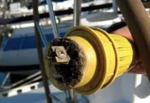
One of the often overlooked maintenance items in the pre-season rush to the water is the AC shorepower system. Barring improper use or some owner fabricated MacGyverism gone bad (jury-rigged adaptors, botched plug installations, etc.) overheating and corrosion are the primary causes of AC shore power cord problems. Charred plugs and receptacles are the most common and are a result of resistance build up due to loose or corroded connections, which in turn generate heat and the potential for fire. The problem is especially prevalent among boats that continually run high energy loads such as water heaters and air conditioning units.
Basic inspections of your AC shore power system are easily accomplished and are well within the ability of any boater. The first step is securing all AC power to avoid accidental shock hazards. Turn off your boats main AC breaker, then the shore pedestal breaker. Next unplug the shore power cord and verify that all other sources of power (such as power on-demand generators and DC to AC inverters) are turned off and their respective breakers secured in the off position.
Start your inspection with the shore power cord itself, ensuring its constructed of proper marine grade components, uses appropriately sized wiring, and is the shortest cord that will get the job done. Always replace cords that show signs of chafe, cracks, split insulation, or those having electrical tape repairs.
Industry standards call for shore cords to have molded-on plugs with sealing flanges or appropriate weatherproof boots. The plugs themselves should be checked each time you disconnect shore power (prior to getting underway for example) or monthly at a minimum, particularly for discoloration or corrosion on or around pins and plug inlets.
By the time discoloration is visible at the front of a plug or inlet, youll typically find that the damage is greater upon opening up the back for inspection. If left uncorrected, the damage will snowball (due to increasing resistance and heat buildup) until it burns a hole through the face of the plug, possibly leading to a fire.
When inspecting your shore power cord its also crucial to check the dock pedestal outlet and your boats inlet receptacle, ensuring both are corrosion free and undamaged. Upon finding a charred power cord plug, many owners simply replace it or the cord itself, only to find the new one also damaged a short time later due to a burned dock receptacle or inlet.
Another good practice is checking the feel of the connection when plugging in. Those that feel loose or don't seem to be making firm mechanical contact likely wont provide good electrical contact either. Avoid using worn or damaged pedestal plugs and report them to marina personal as soon as possible.
For more advice on electrical safety aboard, purchase Marine Electrical Systems, Volume 5, AC Systems from Practical Sailor.
Or, buy the entire Marine Electrical Systems five-part series!
Using an On-Board Generator To Power Your AC
Air conditioning aboard is seldom a problem when you're plugged into shorepower. The difficulties arise when it gets hot and you're underway. Your battery bank and inverter, which do such a nice job for your stereo and your lights, are just not up to the demands for 110-volt AC electricity that an air conditioner or other power-hungry large appliance requires.
The answer? An on-board generator set. A number of modest power output generator sets in sizes suitable for boats as small as 25' to 30' in length are available.
GENERAL CONSIDERATIONS
First, your choice of genset depends on the type of engine you use for propulsion. In other words, if you run your genset on the same type of fuel that you use for your main engine; this simplifies fuel storage, not to mention fueling-up. The same pros and cons of gas vs. diesel in general apply here: Gas engines are cheaper to buy, but cost more to run, are quieter but will give out sooner, etc. Most of the gensets covered in this article are powered by water-cooled engines.
Air-cooled diesel and gasoline generator sets are available, but, with few exceptions, these units are not intended for use on a boat. Some specialized air-cooled diesel engine-powered DC generator sets are available, usually in combination with direct mechanical power drive for such loads as refrigeration compressors and reverse osmosis watermakers. A few manufacturers also make small water-cooled DC generator sets which can be used to provide 100 amperes or more of 12-volt current, allowing operation of modest capacity air conditioners.
HOW BIG A GENSET?
Your first question should be: "Do I need a genset?" The answer is that you do if you run on-board air conditioning, or your boat has huge electrical demands. Otherwise, simplify your life, skip the plumbing and exhaust installations, and save (a great deal of) weight by going with an inverter instead. How big a genset your boat requires depends on the amount of electrical power needed. It is tempting to choose either too little or too much. On the side of too little is the obvious advantage of smaller size, weight, and cost. At the other extreme is the desire to simultaneously power every device on the boat. The best choice usually lies somewhere in between. A good starting point is to estimate your power requirements. Google search "electrical load calculator" or "estimating marine generator loads" and you come up with several sites with calculators that let you input your AC loads to come up with an approximation of peak loads.
Control of most modern, multi-unit, A/C systems can be coordinated to prevent simultaneous starting of compressors. This can be important, because the in-rush current required to start the compressor is a multiple of the running current. Load shedding - avoiding simultaneous use of the toaster, electric coffee pot, electric skillet, and hair dryer when all A/C systems are on - is an intelligent way to keep the maximum needed generating capacity within reason.
When sizing a genset, use the continuous kW rating of the genset rather than the peak kW or kVa rating.
For more advice on the selection and installation of a genset, purchase Marine Electrical Systems, Volume 5, AC Systems from Practical Sailor. Or, buy the entire Marine Electrical Systems five-part series!
Gel Batteries – Are They Right for Your Boat?
Gel Batteries
Gel-cell technology has been around for a number of years now. But the batteries got off to a bad start, largely due to promises of life cycling that were too optimistic. Even worse, there was little or no warning of the voltage limits of the battery (they must be charged at no more than about 14.1 volts). We know many sailors who bought gel cells expecting great performance, installed them in a boat with the standard battery charger (that charges at more than 14.1 volts), then wondered why the batteries failed after just a few weeks.
All gel batteries are not created equal. The big three gel manufacturers- EastPenn, Johnson Controls and Exide-differ remarkably in how they make their products and what they put into them. Gel cells differ considerably from their wet-cell counterparts in that the grid inside is made of calcium/copper alloy. Calcium may be used in starting batteries to enable the battery to give up large amounts of energy for short periods of time, but is less desirable for deep cycling.
How do the gel cells get away with it and why do they use calcium? The first reason is the ability of the battery to use the power from the gelled electrolyte, which has the consistency of wax, instead of taking it from the plates. The plates are not stressed as much in this manner. Secondly, calcium is a very low-resistance material and allows the gel cell to accept a higher rate of charge in the beginning of the charge cycle. Thirdly, gel batteries have the ability to sit for very long periods of time with very little self discharge, even in warm temperatures. In taking the cells apart, it was interesting to note that these batteries continued to show voltage on our meter, owing to the power being stored in the gel mixture, even with most of the internal cells severely cut away.
Another asset of the gel battery is its ability to be sit on its side or end, solving battery space problems, but expect up to a 10% loss of performance. In a pinch, a gel cell could even be built into a semi-dry bilge as it is totally sealed via its special cell caps and operates at a positive internal pressure of up to l-l/2 psi, thus the puckered look of the case assembly at times.
Gel batteries never need maintenance. Their recombination technique replaces the lost moisture in the battery as long as the integrity of the closed cell is intact. A sure way to destroy the battery is to overcharge it, which drives out the oxygen and hydrogen via the cap; the result will be a dried out cell. All gel cell battery manufactures recommend special charging procedures with particular attention to the final charging voltages. And yes, gel batteries do make good starting batteries.
For more information on marine batteries and other electrical systems, purchase Marine Electrical Systems, Volume 1, Batteries from Practical Sailor.
Or, buy the entire Marine Electrical Systems five-part series!


