Photo by Brion Toss
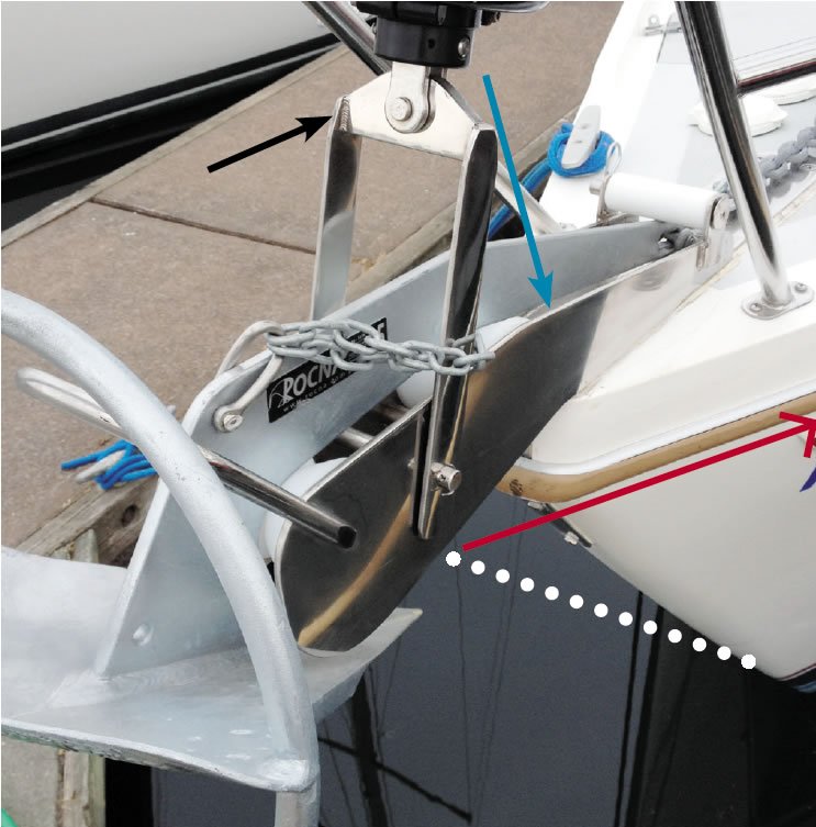
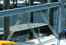
Reader Fred Jensen and his wife, Barbara, of Sandusky, Ohio, pointed out an error in our illustration in the August 2015 issue of Practical Sailor. The photo-illustration depicted a bow-roller and headstay, and lines indicated wire stays with turnbuckles that were required to counter the headstay loads when the boat is under sail. It was the published answer to a puzzle that rigger Brion Toss posted in the May 2015 issue of Practical Sailor in his photo-essay The Hidden Causes of Rig Failure. The corrected illustration appears at right.
The key omission was an arrow (blue arrow near top of photo) indicating the approximate location of the foremost deck fastener (hidden) that will be stressed by a sizable portion of the headstay load, especially when the boat is on the wind. The other lines in the photo indicate additional stays that are required to minimize the loads on the bow-roller/mini-sprit, the deck fasteners, and associated hardware. The red line indicates one of two stays on each side leading aft from the roller and attaching to the hull just below deck level to counteract lateral loads. The white dotted line indicates a bobstay required to counteract the upward pull of the headstay.
Jensen also raised questions about some other details in the photo. He suggested that a solid rod would be a more appropriate material for the bobstay (white dotted line) to counteract the downward anchor loads while the boat is at anchor. Toss and PS Technical Editor Ralph Naranjo both noted that there is some can’tilever forward of the headstay that the anchor could act upon, but Toss concluded that although this can’tilever is undesirable, a stainless-steel rod was unnecessary. He said the headstay and sidestays (red line) are sufficient, and he pointed out that a bobstay made of solid stainless-steel rod would not function well in compression.
Jensen also raised questions about the welded upside-down U-fitting that the headstay attaches to (indicated with black arrow), which puts too much faith in some relatively small welds. Naranjo also was troubled by the U, which introduces an undesirable 90-degree turn in the path that the load follows. Various options would avoid a right-angle turn. For example, two pre-shaped tangs, angled and joined at the top with a toggle, would obviate the need for welding. Alternatively, a more robust welded joint with more surface area would inspire more confidence. Any remedy should keep the headstay toggle oriented as it is. In a proper setup, the toggle will allow the headstay to sag to leeward without stressing hardware (as it is, the torque is too much for the toggle to help). .
Jensen also offered a suggestion on better ways to restrain the anchor by modifying the roller to accept a pin.


