During the time former PS Technical Editor Ralph Naranjo worked as the Vanderstar Chair at the U.S. Naval Academy, he organized a research project that was carried out by first-class midshipmen (seniors) in the Mechanical Engineering Department. The goal was to design a steel box beam jig replicating the perimeter of a Navy 44.
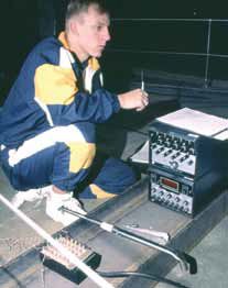
The unbending jig was fitted with a complete lifeline system that could be subjected to hydraulically generated destructive loads. The research tested how such systems fail and measured the load that led to such failure. It was a carefully controlled experiment that tallied input loads, and using strain gauges in numerous jig locations, it measured the effect on all system components.
A hydraulic ram replicated the force exerted by several crew being hurled against the lifelines. Surprisingly, stern pushpit failure proved to be the Achilles heel. Tension in the lifeline caused the vertical legs of the stern pushpit to crimp near their base, and as the structure folded toward the bow, slackening lifelines imposed bending loads on individual stanchions, causing them to fold outward. Each time the test was repeated, the same result occurred due to the geometry of the stern pushpit. Its right-angled legs made it more vulnerable to collapse than the steeply angled bow pulpit that handled more of the load in compression rather than shear.
The net result of this study revealed that when a 3/16-inch, 1-by-19 stainless-steel lifeline has a breaking strength of 4,200 pounds—and as long as there are no defects in the fittings—it’s the strongest component in the system. Other structures will fail well before the wire itself.
In the USNA testing, the stern pushpits collapsed when there was only about 1,200 pounds of load in the wire. Once slack developed in the lifeline, stanchions bent outward, but the lifeline itself never parted.
Tales of broken wire usually involve vinyl coated 7-by-7 stainless steel, and years ago, ISAF Regulations were changed to eliminate the use of coated wire for lifelines. Swages and hardware have also proven to be weak links in the system, but with regular inspection of all components, a crew can catch potential problems. When it comes time to renew the standing rigging, it’s also a good idea to renew the lifelines and hardware.
Many modern cruisers and larger race boats come with 30-inch-high double lifelines. The engineering behind such structures includes a careful look at the deck laminate. The designer/engineer needs to be sure that the point load on a stanchion doesn’t result in crushed core, or even worse, a stanchion torn out of the deck.
On sailboats with an inward-turning hull flange and a deck that has a solid FRP perimeter, this high-density boundary is often located where the outboard fasteners for the stanchion base penetrate. Unfortunately, when a stanchion is loaded with crew weight, the bolts that end up in tension are located at the inboard part of the stanchion base. This area is often part of the cored region of the deck. Better builders “infill” or close off the core in these locations. They insert high-density material during the molding process or add a load-spreading backing plate, rather than simply securing the stanchion with a larger diameter washer.
Damage resulting from deck density variation can be fixed with some epoxy putty and the installation of a G-10 topping and backing plate. These 1/8-inch to ¼-inch-thick pieces of solid laminate are cut a bit larger than the stanchion base. They create a slight mounting plinth and backing-plate that spread loads at the stanchion base. Lifeline stanchions, like a rudder stock, should ultimately fail in a bending mode. If they are stronger than the deck or the hull that supports them, the resulting damage is a hole in the boat. The art of engineering and boatbuilding is coming up with structures that answer such complex challenges.
Make Sure Your Lifelines Are Up To Snuff
Lifelines and stanchions should undergo regular inspection. Common trouble spots include:
- Terminal fittings: Inspect for missing cotter pins and loose terminals.
- Gate hardware: Check regularly or eliminate opening altogether.
- Backing plates: Add topping and backing plates to stanchion base.
- Wire coating: Use uncoated wire.
- Pushpit reinforcement: Have a diagonal tube welded into the pushpit (stern pulpit).
- Split bow pulpits: Beware of open-split, two-leg bow pulpits. One piece pulpits spread loads to both port and starboard sides, even when only one side of the lifeline is tensioned. Split pulpits lose this load sharing ability and are inherently weaker.
- Over-accessorizing: Beware of compromising the stern pushpit with davits, antenna brackets, arches, and other ancillary loads that are vulnerable to breaking seas.


